Mechanical System
Gantry
The gantry consists of a frame constructed primarily from imperial 1010 aluminum extrusion, with certain spans constructed using metric 2020 aluminum extrusion. The aluminum extrusion components were attached using ¼-20 pan head bolts and blind joints, maximizing rigidity and reducing the project parts count.
All extrusion pieces were cut, and then squared and standardized using a knee mill. This resulted in a gantry that is square within all axes, and extremely rigid. Metric 2020 extrusion was used across all spans where linear rails were affixed, as the MGN-9 rail we used did not fit nicely on the imperial 1010 extrusion.
The somewhat unconventional overall design of the gantry was specifically chosen to suit our task. Usually, in cartesian systems, the goal is to reduce the unsupported length of the crossbar, in order to promote rigidity and precision. We elected to depart from this convention, as our system is optimized for speed in one axis only, and running the crossbar lengthwise (parallel to the axis of rapid motion) meant that there was minimal transverse loading on the crossbar. This trade-off, of a longer unsupported span with comparatively less lateral loading, allows us to move the toolhead extremely quickly without sacrificing rigidity or precision.
We also took care to integrate robust belt tensioning mechanisms across both the x and y axis. This helped to contribute to the rigidity of the system and allowed us to reach high travel speeds.
Flipper
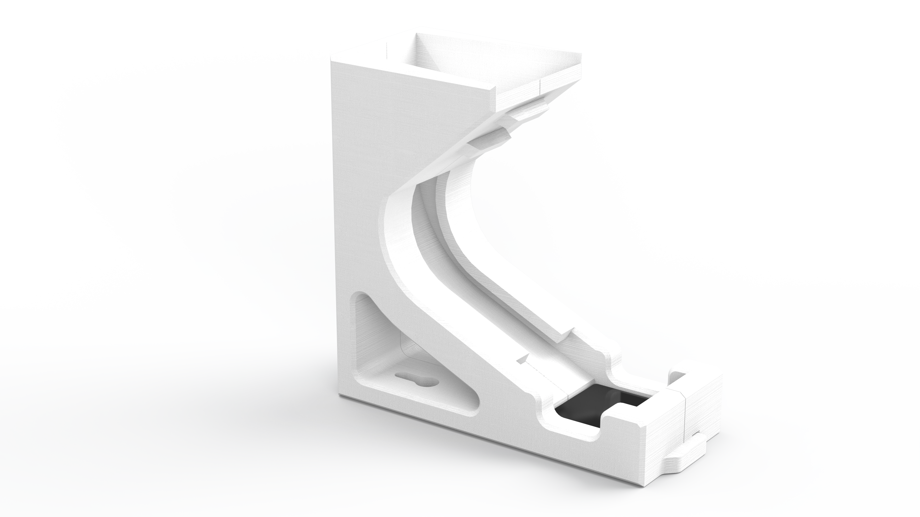
The flipper mechanism is a gravity fed slide that allows the gantry to turn tiles from their white side to the black (or vice versa). The top of the slide has a wide opening that funnels the tile toward the inversion point. Then, the slide guides the flipped tile into the pick-up zone where it passively aligns with the trough. After making a simple sketch model of the flipper geometry to confirm viability, we used iterative design to eliminate potential reliability issues over 8 unique prototypes.
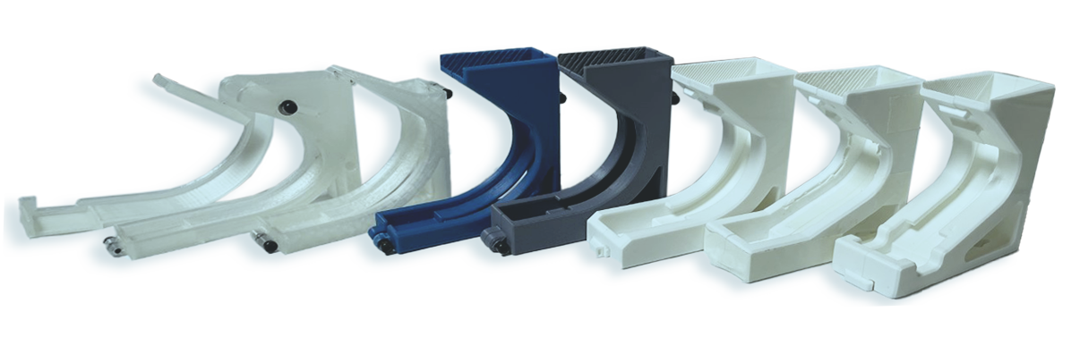
Some of the failure modes we experienced during testing involved the tiles not flipping at all, tiles coming in at an angle and getting stuck, tiles sliding too fast and bouncing out of the pick-up zone, tiles sliding too slowly and not making it to the bottom, and tiles rubbing against the walls of the pick-up trough causing them to fall off during pick up. The end product is heavily optimized to mitigate nearly all of these potential failure modes.
Toolhead
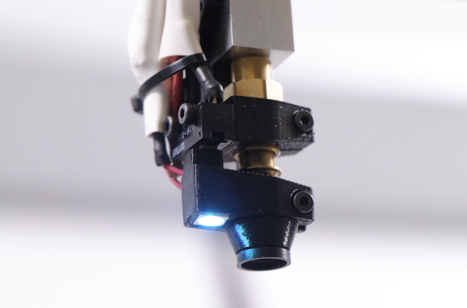
The gripper toolhead is responsible for picking and placing the tiles. The design features 100 mm of vertical travel, which allows the tiles to be lifted up from the build plate to the height of the flipper drop zone. The gripper relies on a suction nozzle sold for use in traditional PCB pick-and-place machines. The nozzle is powered by a 24 volt diaphragm air pump which is mounted in the main control box. This was done to eliminate toolhead mass and promote faster movement.
The toolhead also features limit switches to detect the extremes of toolhead extension. The switches are also used to probe each tile prior to pick up. This helps to compensate for a variable build plate height and allows tiles to be picked up reliably every time.
Pneumatics
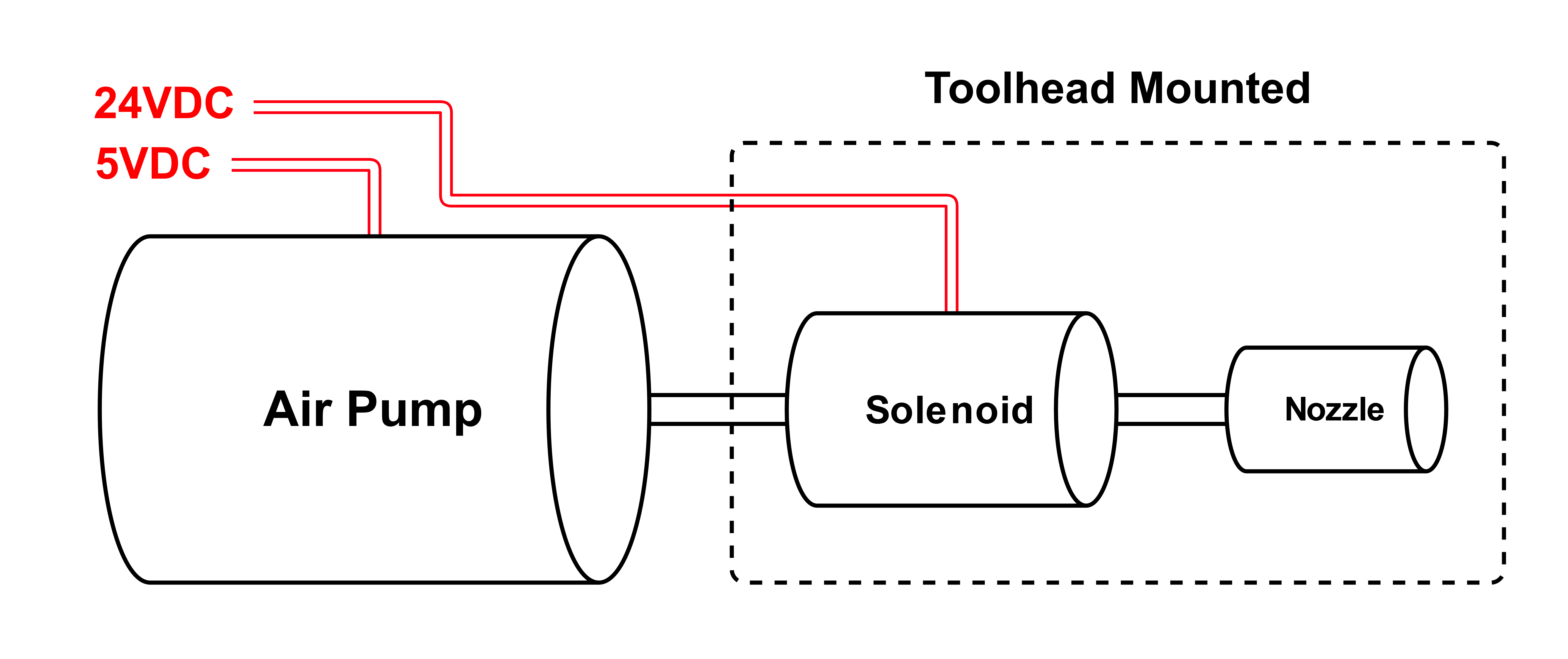
Although our pneumatic system is relatively simple – containing only three components and the tubing to connect them – we carefully choose them for reliability. The air pump, solenoid valve, and nozzle are similar to those found on open-source pick-and-place machines. While remaining budget-friendly, these components are designed for thousands of hours of operation, making them ideal for our application. The pump was mounted in the electronics box and a tube was routed to the tool head through the toolhead umbilical. Along with the nozzle, we mounted the solenoid air valve on the toolhead so that vacuum control at the nozzle was precise as opposed to in the electronics box with the air pump. As a result, tile manipulation was precise due to faster pressure changes at the nozzle.
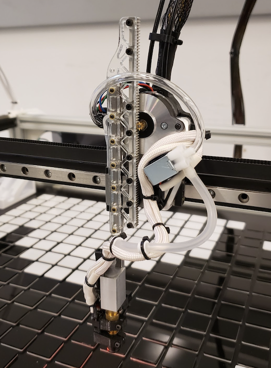
The pump required 24VDC, while the solenoid required 5VDC. We wired both to the FYSETC Spider with their respective voltages. We used a mix of silicone and vinyl tubing, as we found some of each. The silicone tubing between the solenoid and nozzle helped with flexible cable management while the vinyl tubing between the pump and solenoid ensured the tubing did not kink when the toolhead moved within the work area.
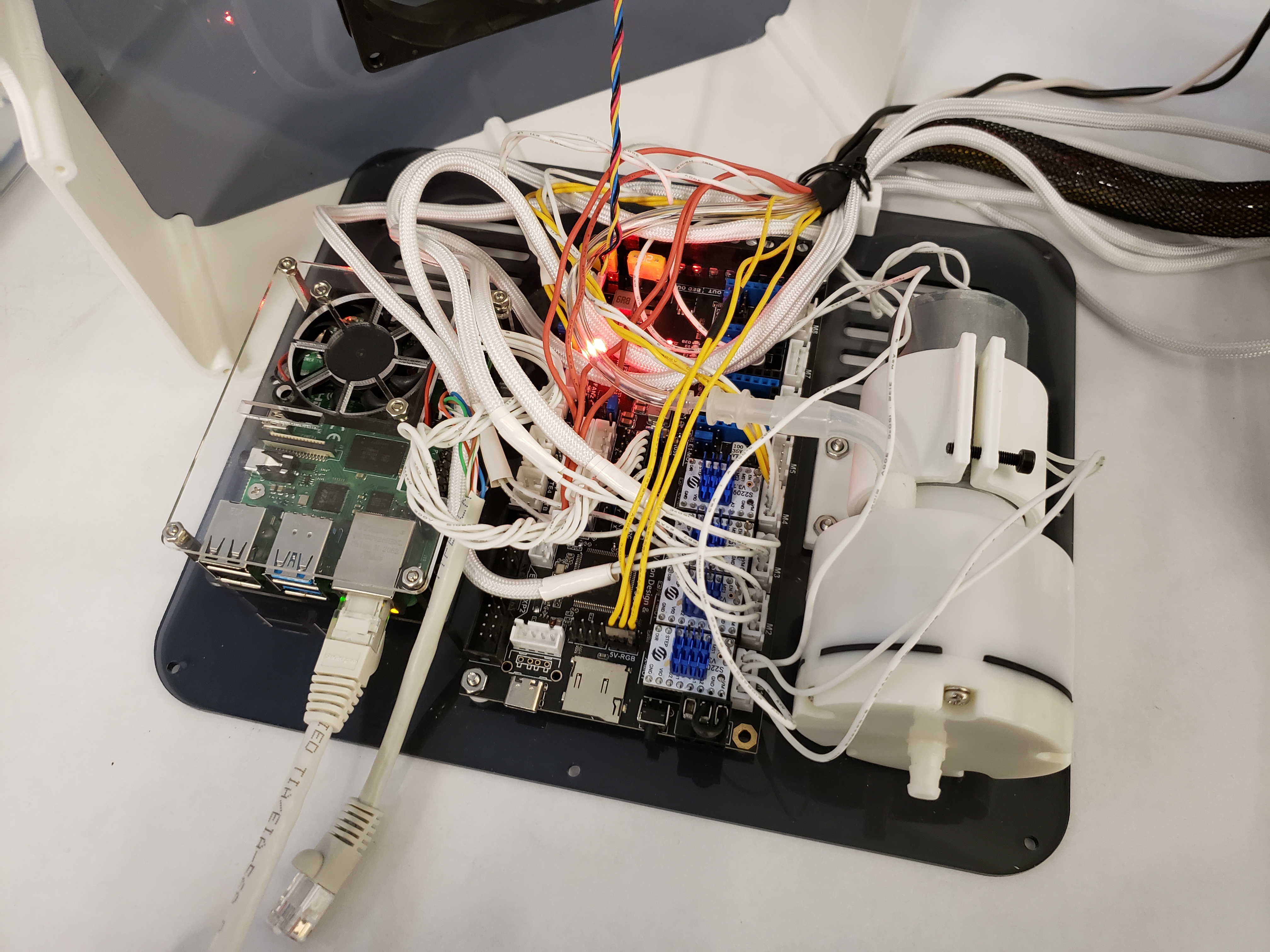
Because an airtight seal through the entire pneumatics line was not required, we forgoed proper tube barbs and slipped the flexible silicone tubing and semi-flexible vinyl tubing over the outputs on the pump and solenoid. Combined with our overkill air pump, at no point did we have reliability issues with the pneumatics line.
